Never worked with circuits and breadboards? Then you've come to the right place: All the steps from the bare Arduino to the running program - without any prior knowledge, without having to write your own code.
Hardware and software
The project for this tutorial is very simple: An LED should light up for 1 second and then stay off for 1 second - in other words, it should flash. The hardware used here is an Arduino Mega 256 , but the procedure is identical for almost all models. In addition to the board, you also need the following components: A resistor with up to 1 kiloohm, an LED , two connection cables , a breadboard and of course a USB connection cable for the board. These things should be in every Arduino entry-level kit. By the way: A breadboard is a breadboard that is used to set up circuits with plugging in instead of soldering.
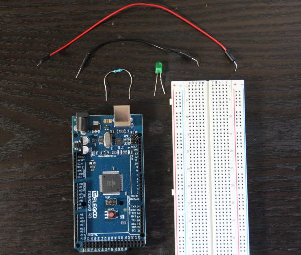 Materials required.
 The get Arduino software directly on the homepage , any CDs from entry-level sets, you can safely ignore. The code for the tutorial shown here is supplied directly, as it is largely one of the official beginners tutorials. In the (English-language) Arduino documentation, these are unfortunately a bit superficial for real beginners. In addition, the original does not use the breadboard: Of course, the LED and resistor can also be connected directly to the Arduino board, but with breadboard it is easier and for real, more complex projects you have to be able to handle it anyway..
Build hardware
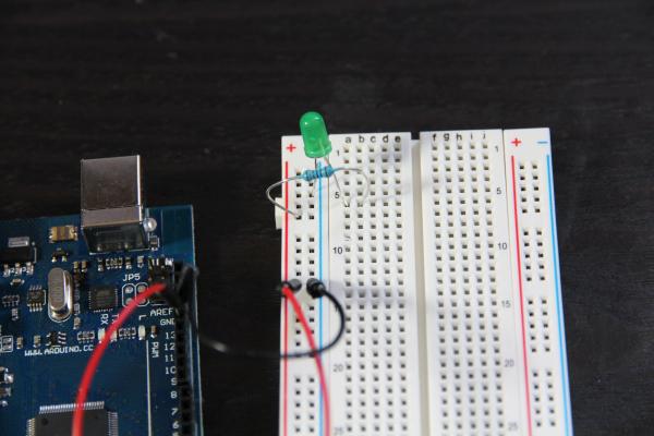
First you have to set up the circuit : Current from the Arduino flows via the breadboard connection D13 through the resistor, through the LED and back into the board, here of course the GND connection (grounding). The D13 connection is connected to the onboard LED of the Arduino board, which is why the external LED can also be controlled via it.
First connect " GND " on the Arduino board to a "Minus" socket on the breadboard. Briefly for information: In the outer areas with "+" and "-" the connections are longitudinal, in the rest of the area they are transverse. Which slot you choose does not matter - but it is best not to start at the very edge so that there is still room for possible future expansions. Here in the picture it is line 13.
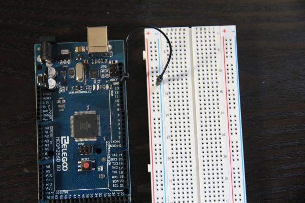 Ground is connected.
 Now connect " D13 " to the "Plus" socket next to the "Minus" socket you just used. This guarantees the power supply..
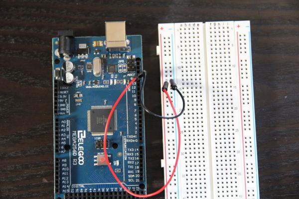 The pin of the internal LED, D13, is connected.
 Now take the LED to hand: A metal pin is a little longer - the plus pole . This goes in the "a" column of the breadboard (here line 6), the shorter pin in the "minus" column .
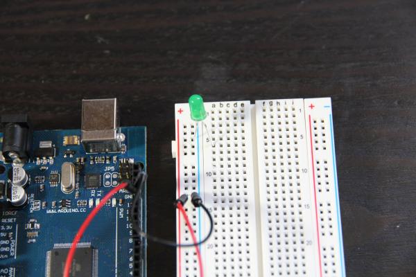 The longer pin goes in the "a" column.
 So that the current does not flow unchecked through the LED and thus destroy it, a resistor of up to 1 kiloohm is now placed in the "plus" column and in the "b" column in the same row as the LED. The current can now flow from "D13" through the resistor and LED to "GND".
 Last but not least, the resistance.
 And here's an overview again:
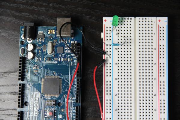 The hardware is now ready.
 Set up software
Now install the Arduino IDE and connect your Arduino board to the computer via USB. This should now be recognized and set up by Windows. Then start "Arduino" from the start menu. First of all you have to tell the software what kind of Arduino board it is, which you define via " Tools / Board ".
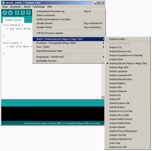 Select board.
 Then configure the correct connection via " Tools / Port " - usually this is the only connection specified besides the standard " COM1 ", labeled with the name of your board. Your setup is now complete and you can start programming - or use a ready-made sample code.
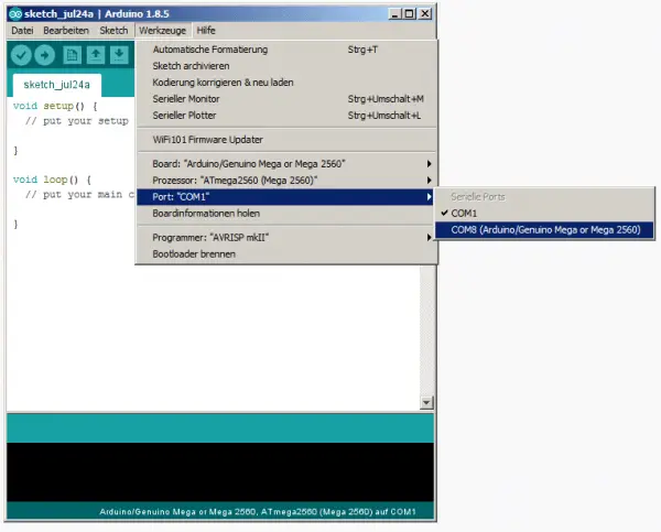 Select port.
 Upload program
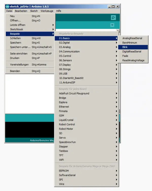
As promised, you do not need your own code, the flashing LED is already included as a project as a standard example. Open it via " File / Examples / Basics / Blink ". The code is extremely simple and well explained, albeit in English - so here again in German:
// The setup function runs once when switching on as a start for each program (sketch).
void setup () {
// D13 (LED_BUILTIN) is set as output.
pinMode (LED_BUILTIN, OUTPUT);
}
// The loop function simply runs endlessly.
void loop () {
digitalWrite (LED_BUILTIN, HIGH); // LED voltage is set to high, the LED lights up.
delay (1000); // Waiting time in milliseconds - the LED continues to light.
digitalWrite (LED_BUILTIN, LOW); // LED voltage is set to LOW, the LED goes out.
delay (1000); // Waiting time in milliseconds - the LED is still off.
}
To activate the program, you have to upload it to the Arduino board, which you do via [CTRL] + [U] > " Sketch / Upload " or the small arrow symbol in the upper left corner of the program window. After a short time you should get a message that the upload has been completed. You don't have to do anything else, the blink sketch should run. With the standard values, the LED should flash every 1 second. You can of course change the values as you wish.
 The blink sketch in the IDE.
 When uploading, many users report error messages, the forums are full of them. The most common cause is likely to be an incorrect or forgotten configuration of the port and Arduino board - so check and adjust if necessary. Outdated software could also be responsible, which is why a version from a CD that may be supplied should not be used. You can get further help via " Help / Troubleshooting ".
What's next?
You now know how to get programs on the Arduino, how to "tap" the Arduino and how such a breadboard works. And with this knowledge you should now be able to imitate most projects on the Internet. Basically, it usually boils down to the fact that you get the finished code and otherwise "only" populate a breadboard. However, this can be quite complex at times. Programs like the "Blink" script used here, called Sketch in the Arduino world, are simple text files with the ending "ino", which are started with a double click in the Arduino IDE.
Completely own projects are certainly still a few hours away from dealing with the scripting language and the basics of electronics. We therefore recommend the other sample projects supplied,the " Built-in Examples ". Although they are in English, they are so taciturn that you basically only have to recreate the breadboard using the illustration and upload the associated sketch.